
By: Edwin Weijdema
 In this third post of the multi-post Three Dimensions of Storage Sizing & Design we will dive deeper in the dimension: Use and specifically the application Workloads part characteristic Speed. Depending on the application workload requirements, you will need to size the storage system for The Need for Speed. So let us dive deeper into IOPS.
Speed with computer storage devices like hard disk drives (HDD), Solid State Drives (SSD) and Storage Area Networks (SAN) is expressed in Input/Output Per Second (IOPS). Applications will interact with storage for retrieving and storing data.
What are IOPS?
IOPS are expressing the performance a storage device can achieve with completing read and write commands in a second. We will look at a simplified example for how many IOPS a disk can deliver within the boundaries of physics. These are called the back-end IOPS. Simply put how many IOPS can the disk(s) in the back-end deliver. Every disk in your storage system has a maximum IOPS value that is based on a formula, namely:
IOPS = 1000ms / (Average Seek time in ms + Average Latency in ms)
- Rotational speed is measured in revolutions per minute (RPM). How fast the disk platters are rotating inside the disk.
- Average Latency is the time taken for the platter to undergo half a disk rotation. Why half? Well at any one time the data can be either a full disk rotation away from the head, or it might already be right at it. The time taken for a half rotation therefore gives us the average time it takes for the platter to spin round enough for the data to be retrieved. To calculate the average latency take the RPM and use the following formula: Average latency = ((60 seconds / RPM speed)/half rotation 2)*1000ms.
- Average Seek time is the time in milliseconds (ms) it takes for the disk’s head to position itself over the track being read or written. When the I/O request comes in for a particular bit of data, the head will not be above the correct track on the disk. The arm will need to move so that the head is directed over the correct track where it must then wait for the platter spin to present the target data beneath it. As the data could potentially be anywhere on the platter, the average seek time is time taken for the head to travel half way across the disk. There are both read and write seek times; by taking the average of those two values give you the average seek time.
Theoretical IOPS for Calculation Sizing
For disk (HDD and SSD) I normally use the numbers in the following table as a rule of thumb to calculate raw backend random IOPS from disks. Raw? Yes RAW, because we don’t factor in caching/buffering in the whole chain (disk, controller, head, adapter, hypervisor, operating system, application, workstation), RAID influence, interface connection, driver configurations, queue depths, etc. But lets keep this simplified to have a workable model to calculate the IOPS from the backend easily.
| Disk RPM | IOPS ~ Average | IOPS range | Average Latency (ms) |
| 5.4K HDD | 55 | 50-65 | 5,6 |
| 7.2K HDD | 80 | 75-100 | 4,2 |
| 10K HDD | 120 | 120-140 | 3,0 |
| 15K HDD | 180 | 175-210 | 2,0 |
| SSD (WI) | 40000 | 65000-115000 | 0,1** |
| SSD (MU) | 8500 | 7000-25000 | 0,1** |
| SSD (RI) | 3000 | 2000-15000 | 0,1** |
| BSSD (ICE) | 20000 | 5000-85000 | 0,1** |
** Latency on SSD is not because the spinning of the disk (duhhh no mechanical moving parts in here, latency on SSDs is on average 0.03ms!), but the network chain between the processing and the SSD. For more insight in different SSDs and their IOPS number take a look at this wiki page.
Front-End versus Back-End IOPS
Often you will hear that an application will need 2.400 IOPS and that it communicates with 64K block size. Like for instance Microsoft SQL Server 2014 OLTP Log files. These are the so-called Front-End IOPS, but to let that data land on the Back-end storage systems they generate Back-End IOPS.
Size does matter!
Lets compare a storage system that stores the data with a block size of 128K and a storage system with 4K blocks.
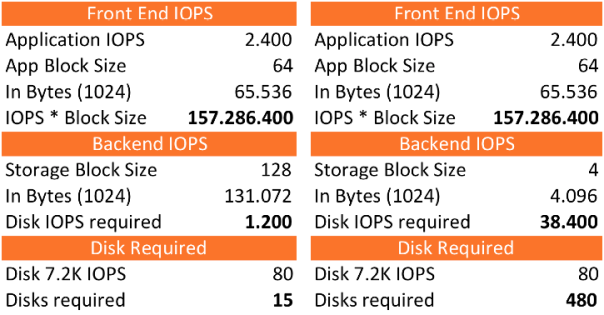
We will see that it will require 15 disks and 1.200 IOPS in the back-end when the storage system can store with 128K blocks. If you store this same I/O stream on a storage system that utilizes 4K blocks you will need a whopping 38.400 IOPS. To back those incoming IOPS you will need to run with 480x 7.2K NL-SAS disks!!!
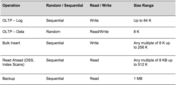
Like most applications you can have different front-end IOPS and block sizes per workload, even within one application. Microsoft SQL 2014 server is a good example that uses a different disk access pattern as shown in the following table:
Info: Oracle DB default block size is 8K, and the Hadoop default block size is 64M.
Ok now we know that size does matter but why should you care? Most SQL Server performance issues in (virtual) environments can be traced to improper storage configuration. SQL Server workloads are generally I/O heavy, and a misconfigured storage subsystem can increase I/O latency and significantly degrade performance of SQL Server. Running Microsoft SQL server on VMware? Checkout this valuable resource about Architecting Microsoft SQL Server on VMware vSphere.
Playing the Tetris Storage Block game
With virtualization we introduce another layer into the I/O path. So what about all those different layers? If you look at a complete stack in a datacenter you could see an Application running on an Operating System that is installed within a VM. This VM runs on a Hypervisor, where this hypervisor talks to a storage backend and eventually lands on spinning disk and/or flash.
Example:
- Application – Microsoft SQL server – Logs 64K
- Operating System – Microsoft Windows 2008R2 – 4K
- Hypervisor – VMware vSphere 6 (ESXi) – runs VMFS-5 data store – 1M Unified Block
- Storage – NexentaStor 4 – 128K Block
- Disk – SanDisk BSSD – 16K block with a 4K Sector size
HDDs have a block size of 512 Bytes or 4K. With the up rise of flash we see the Block size being increased. Looking at the SanDisk – Board Solid State Drive (BSSD) card with its ICE chips gives the flash card 8TB storage capacity, which has a 16K physical block size (virtual page) and a logical 4K or 512 bytes sector size.
Block Size versus Sector Size
While sector specifically means the physical disk area, the term block has been used loosely to refer to a small chunk of data. Block has multiple meanings depending on the context. In the context of data storage, a filesystem block is an abstraction over disk sectors possibly encompassing multiple sectors. Most file systems are based on a block device, which is a level of abstraction for the hardware responsible for storing and retrieving specified blocks of data, though the block size in file systems may be a multiple of the physical block size.
Determining block size while formatting the file system in an OS is a case of tradeoffs. Every file must occupy at least one block, even if the file is zero bytes, so there’s something for the file’s metadata to be attached to. Unless you can guarantee that your files will ALWAYS be some multiple of the block size in size (e.g. in a 4k block OS, all files are 4k), there’ll be a certain amount of wastage for the files that don’t exactly fit within that block.
It’s all about Balance
Going with small block sizes is good when you need to store many small files. On the other hand, more blocks is more metadata, so you end up wasting a portion of your storage system on overhead, tracking the location of all the files. On the flip side, large blocks means less metadata, but also mean greater wastage when you’re storing small files. e.g. a 4 byte file stored in a 4k block wastes 99% of that block.
Sectors are an obsolete concept in modern drives. They existed when “locations” on a drive were specified by the old CHS (cylinder, head, sector) definition, which wasted a lot of space. All modern drives use LBA – logical block addressing, so sectors don’t really exist anymore. However, an OS can still chain multiple blocks/sector into a single logical OS-level block to reduce space. E.g. “every 8 real blocks/sectors on the drive will be considered 1 block by the Operating System”. A sector is a unit which is normally 512 bytes or 1K, 2K, 4K etc. depending on hardware.
When the logical block size of a drive is not in multiples of 512 bytes, geometry information is not available because the file system does not support other block sizes. Linux does not discover such drives, and Windows shows such drives in disk management, but does not allow you to execute any operations on them.
Partition Alignment
Aligning file system partitions is a well-known storage best practice for database workloads. Partition alignment on both physical machines and VMFS partitions prevents performance I/O degradation caused by unaligned I/O. An unaligned partition results in additional I/O operations, incurring penalty on latency and throughput. Lets look at the example we used before with the SanDisk BSSD, this BSSD uses 16KB Blocks and 4K sector sizes. For protection of the data and increasing the total amount of IOPS and throughput we stripe/mirror several cards together.
Properly Aligned
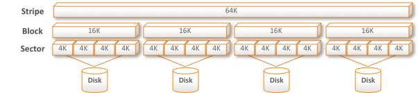
If a workload with blocksizes is properly aligned you will see that it looks like a Tetris game filling up and because of striping over more than one disk in storage systems you really want to get the most out of it.
Mis-Aligned
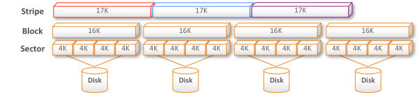
When for instance a block size of 17K is chosen for the stripe it means that you will have all kinds of problems. The Writes and Reads will cross sectors, blocks and disks carving them up into all kind of chunks and messes the data stream up with lots of additional I/O, latency and fragmentation.
Aligning with VMware vSphere 5.x or later
vSphere 5.0 and later automatically aligns VMFS-5 partitions along a 1 MB boundary (1MB Unified block). If a VMFS-3 partition was created using an earlier version of vSphere that aligned along a 64KB boundary, and that file system is then upgraded to VMFS-5, it will retain its 64KB alignment. 1 MB alignment can only be achieved when the VMFS volume is create using the vSphere Web Client.
More to the equation
There is more to the whole equation about Speed than discussed so far. Factors like:
- Protection levels like for instance RAID, where you get write penalties or multipliers with Read that effect the overall Speed. I will dive deeper and explore this further in the next blog part(s) around the Storage Dimension Protect.
- Caching on several levels in the whole I/O data path like Application, OS, Hypervisor, Host, HBA, Storage System, Disk, etc. which makes it much more complicated to predict the Speed and IOPS.
- Data reduction techniques, which I will highlight in the Storage Dimension Manage.
In the next part of Three Dimensions of Storage Sizing & Design we will dive deeper into workload characteristic Throughput (MB/s).